|
|
|
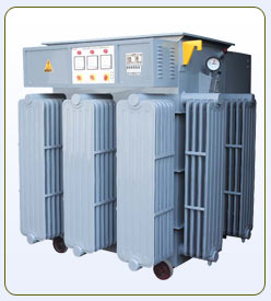
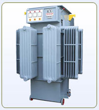
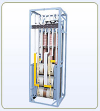
Balanced Type
AVR |
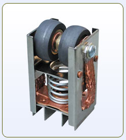
Carbon Roller |
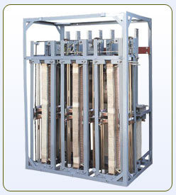
Inner view
of AVR |
ADVANTAGES
 Reduction in Breakdown of the electrical equipment.
Energy Saving 5 % to 10 % possible
Improvement in power factor
Reduction in MDI
100 % depriciation as per income tax Act.
| Chart depicting
Reduction in Break down at different voltage level |
Input Voltage
Variation |
Possible
Reduction in Break down of Electrical Equipments
|
Approximate Power
Saving
(Mainly at Higher Voltage) |
380-420 Volts |
Normal Fluctuation |
Stablizer required only for
Computerised CNC Machines or for Lighting System |
360-440 Volts |
Upto 20% reduction in Break
down of electrical equipments |
Power Saving upto 5% |
340-460 Volts |
Upto 60% reduction in Break
down of electrical equipments |
Power Saving upto 7% |
320-480 Volts |
Upto 80% reduction in Break
down of electrical equipments |
Power Saving upto 10% |
The nagative impacts of higher voltage on motor below 10 HP are very much apparent
as given in the following table.
| The
table below compares the behavior of 5 H.P. Motor
at different voltage. |
Input Voltage
|
Current
Consumption |
KVA |
PF |
400 |
11Amp |
7.6 |
0.8 |
420 |
10% more |
16% more |
0.7 |
440 |
20% more |
40% more |
0.61 |
460 |
30% more |
49.8 % more |
0.57 |
1. It is
clear from the above chart that with the increase in
supply voltage the input current also increases
and the power losses also increases in motors which
results in premature failure of winding.
2. This
increased current of electric
motor results in over loading of cables, switch gears
and transformers.
3. Due
to increase in current the Power Factor of the system
decreases, which needs extra capacitors to maintain
the P.F which results in over loading of switch gears
etc.
The higher voltage highly effects the life and lumination of lighting equipments. If the lamps are provided according
to higher voltage then illumination decreases during
the normal voltage period.
| Table below
gives the lumens and life characteristic of 60 watt
coil lamps at different voltage rating. |
| Lamp
rating |
Lumen
& life at 230 V |
Lumen
& life at 240 V |
Lumen
& life at 250 V |
| 230 V
60 W |
710.lumen
1000 Hr |
820.lumen
575 Hr |
943.Lumen
338 Hr |
| 240 V
60 W |
605.lumen
1740 Hr |
700.lumen
1000 Hr |
804 lumen
528 Hr |
| 250 V
60 W |
523.lumen
2956 Hr |
605.
lumen 1700 Hr. |
695
lumen 1000 Hr. |
It is interesting to note that if a bulb designed for
230 v operated at 230 v or 240 v lamps operated
at 240 v or 250 v lamps operated at 250 v give comparable
performance in respect of lumens out put & life.
The information given in the table
reveals the way how a 230 v lamps would perfom when
opretered at 240 v & 250 v. At higher voltage, though
the lumens of bulb increases
but life decreases considerably.
Therefore the life and efficiency of the lighting equipment will be
maximum if the voltage supplied to it is accroding to the rating
of lighting equipment.
From the above mentioned observation
it is clear how important is the installation of the
stabilizer and maintainting 400 v / 230 volts.
The Motor, lighting equipment and other electronic equipment will
operate up to their maximum efficiency,
consuming normal power as per rating and we can avail
optimum life of motors and switchgear.
| The Table below
compaires the behaviour of 60 watt lamp (design for
230v) at different voltage |
Voltage |
Current
in Amp. |
Watts consumed |
Luminous
Intensity |
Life
in Hours |
230 |
0.26 |
60w |
710 |
1000 |
240 |
0.27 |
64w - 8% more |
820 |
575 |
250 |
0.28 |
70w - 16.6% more |
943 |
338 |
260 |
0.29 |
75.4w - 25.6%
more |
1073 |
200 |
270 |
0.31 |
83.7w - 39.5%
more |
1213 |
100 |
Advantage of AVR than Transformer
with OLTC:
The unit which have already installed OLTC with their
transformers also required stabilizer because tapping
of OLTC is changed when problem of very high or low
voltage is observed, on the other hand AVR Moniter and
Control output voltage continuously. However in case
of already installed transformer with OLTC the input
range of stabilizer can be kept low.
Comparision
with Conventional Type AVR |
| GNEW
MAKE AVC |
Conventional
Stabilizer |
| Life
is 15-20 years |
Life
is 2-3 years |
| Efficiency
(99 to 99.5%) |
Efficiency
95 to 97 % |
| Suitable
for 100% load |
Only
30-40 % load capacity |
Components
GNEW Servo voltage stabilizer consists of the following items
:-
1. Linear
type, plus / minus type, vertical rolling contact type
regulator
The voltage regulator is a continuously tapped auto transformer
with core and coils similar to those of an orthodox
thransformer. A mainframe supporting the completely insulated
coils and is housed in an oil cooled sheet steel
tank.
Carbon Rollers move on both sides of the winding, in opposite
direction, to increase or decrease the incoming voltage.
The effect is to produce a variable voltage of either
negative or prositive polarity, which is injected into
the buck boost double wound transformer.
The contact carrier is driven by a fractional horse
power high torque motor which is coupled to the chain
drive. Limit Switches operated by the carrier are fitted,
to prevent overrun.
2. Double
wound buck / boost transformers
Buck-Boost Transformer. - This is a
conventionally designed double wound tranformer housed
in regulator tank or separate sheet steel tank and it
confirms to the latest Indian standards.
The secondary of the buck boost transformer is connected
between the mains and the load while the primary has
its voltage controlled by the motor driven regulator.
A Voltage of either positive or negative polarity, as
the case may be, fed to the primary. It induces the
same to the secondary thus adding to or substracting
from the incomming line voltage.
 |
| |
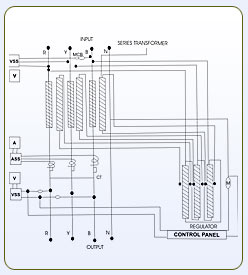 |
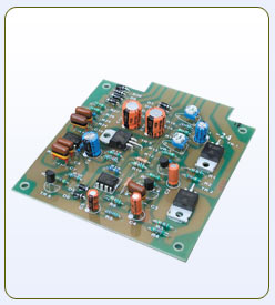
3. Electric
control circuit and meter panel
Control Panel - It is mounted on the
top of the Servo Voltage Stabilizer. A voltmeter and
an ammeter are incorporated in the panel to read output
voltage and load current reading. Two switches, one
for auto / manual mode and other for increasing/decreasing
the voltage on manual mode are provided. A potentiometer
is also provided to set the voltage to required output
at Auto Mode.
A solid state sensor unit (IC Based) continuously monitors
the output voltage from the stabilizer and any error
in voltage is amplified to operate the high torque servo
motor in the variable transformer.
Secondary Components
1. Indicating
& Measuring Equipments :-
(a) Volt
meter analogs / digital type, indicating input and ouput
volts.
(b)
Ammeter analogs/digital type, indicating input &
output current.
2.
Mode switch for manual or Automatic Mode Selection
3. Out
put volt selectability level switch
4. Senscetibity
level selectability switch
5. MCB
Box provided for control panel
Optional but user friendly Features / Components.
1. Over
load protection, thermal or solid state to switch off
unit if the load attains higher value than the rated
current.
2. Over
and under voltage protection can be provided to switch
off unit if the out put voltage found above or below
certain value (preset).
Ranges & Models
Single Phase - 3KVA to 30 KVA
Three Phase - 20 KVA to 5000
KVA
Types - Balance Type & unbalance
type
Efficiency Chart
input
/ output chart |
| Input
voltage |
360-460
Volts |
340 -
460 Volts |
320 -
480 Volts |
300 -
480 Volts |
| Efficiency
|
Above
99.5% |
Above
99.3% |
Above
99% |
Above
98.5% |
Application : - Every type of Industries can
be benefited by its application but the plant running
for 24 hours can achieve wonderful
advantage by instalation of automatic voltage controllers.
| Textile
& Hosiery Mills |
Engineering
Units |
FoodProcessiy
units. |
| Residential
Complex |
Hotels
|
Hospitals. |
| Rolling
Mills |
Oil
& Vanaspati Plants |
Solvent
Plants. |
| Rice
Shellers |
Paper
Mills |
Rubber
Industries. |
| Clubs
|
Flour
Mills |
Tea
Estates. |
| Tube
Mills |
Footwear
& Leather Units |
etc. |
|